

|
Trix and Trix-Express are trade marks and registered trade marks of Trix Modelleisenbahn GmbH & Co. KG, Göppingen/Germany. Trade marks or product names mentioned are trade marks or registered trade marks of the respective owners. |
|
MRE Techology 1. Concept |
|
Wiring:
In the original planning and in the first time the layout was made of 5 segments. To keep the mobility of the layout, all segment are connected together with electrical connectors with 24 contacts each.
Because of the conventional DC operation of the layout, all switches for turnouts and signals are build into a central signal box with schematic track plans for easy operation.
The complete layout power supply is also centralized in the signal box with conventional transformers providing 5V, 12V DC and 16 Volt AC.
The signal box is connected to the layout segments No.1 and 3 with 2.5 meter long cables and then ongoing to the segments No. 2, 4 and 5. with more connectors. |
|
Block and rotary wiring:
On my earlier layouts each track section was connected to two old DC throttles for Trix-Express operation according to the old Trix manuals (Block wiring). This was good to run two trains independent on each section (Block) at the same time with several switchable track sections to store trains (Trix-Express three rail system/Twin-Train-System) But if a train wants to cross between two blocks, the throttles/Cabs in each block had to be adjusted to same level to avoid short-circuits. If you have a large layout, you could potentially add more cabs and more operators to control different parts of the layout; and you could add rotary switches to dial in which cab is controlling a certain block.
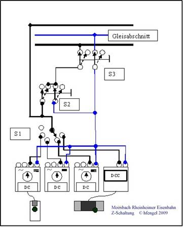
This method of model railroad wiring is referred to as cab control wiring (Z-wiring). I use commercial rotary switches (S1) with 5 contacts to control the blocks of Moosbach depot, Moosbach station, track 1 and 2. In 15 years I added two more segments: Rheinheim station and a functional overhead wire as a separate block. If you select a position on a rotary switch you choose also one of the throttles. If you do this also for the next segment with the same throttle, you have connected two blocks together, so a train can cross these blocks. Meanwhile other blocks can operate with other throttles maybe also in different operation modes. Cab control wiring enables variable operation (modes) with different throttles like DC “walk around” throttles (WAC) or cabs, DC throttle with Trix-EMS operation or DCC operation with Trix Mobile station WAC. Additional to normal Trix-Express operation (3–Rail) I have created 15 years ago the following wiring to select also 2-rail operation in each block. |
|
Track segments:
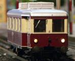
For the Trix-Express operation both tracks are connected together for a easy operation of turntables and reversing loops. TE Engines can pick up power from both rails and the 3rd rail in the middle.
2-rail or 3-rail operation can be selected with switch 2 (S2)
In both operating modes all sidings can be switched off to store all kind of trains regardless if they are 2- or 3-rail, DC or DCC. For this, the sidings are disconnected on two poles (rails) with switches (S3).
Z-wiring/Cab control/rotary wiring: After choosing 2 or 3-track operation with S2 on each block, you can select with a rotary switch S1 one of the following throttles: · DC with WAC for DC engines, · DC with Trix EMS for DC and EMS engine · DCC for DCC engines. · Its also possible to disconnect each block completely to be able to troubleshoot electrical problems.
Theoretically its possible to add more systems very easy to this concept like Märklin AC, MM, Delta, MFX, etc.
|
|
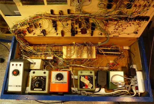
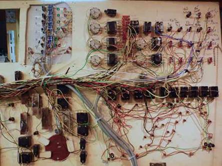
Inside of the switch box, you can see above the throttles the 270 pads for the electric connection to the layout and additional transformers for powering lights, turntables, Faller-Car, Servos for action, switch engines, barriers and signals.
The wiring is made according to DIN VDE 0100 with a separation of 220 Volt and 12Volt. All 12V-kabels are marked for identification with numbers on the solder pads and switches. The wiring documentation is now including 20 pages and allows troubleshooting in minutes.
The connection to the layout is provided with two old telephone connectors with together 270 contacts. With this connectors the signal box can be separated from the layout within minutes.
|
|
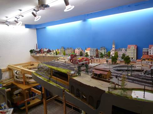
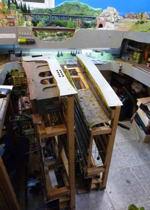
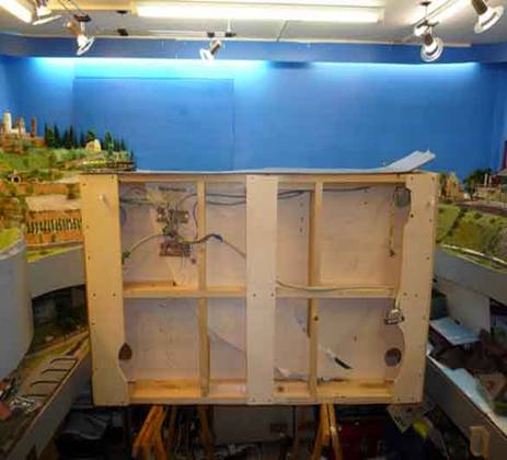
This model railway layout was planned and built from the early beginning in segments to secure most of the layout at possible moves.
Each segment is planned and limited to a size of 1,00m x 1,10m.
The framework is build as open grid girder to get lightweight but robust segments. All segments are settled on wooden support beams which can be adjusted in height according to the floor.
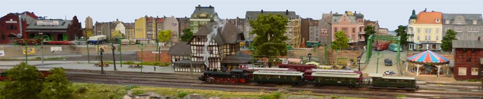
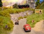
On the picture to the left you can see the station of Bad Moosbach made of three segments together with three little segments carrying the city front settled on a framework mounted to the wall |
|
The switch box has a central power switch and a separate emergency shut off switch on the floor which allows to get the layout powerless in seconds.
The switch box is mounted on an old office chair frame with rollers and can be adjusted in the high. In non operational times, the switch box is stored under the layout. Also for security reasons there are two main switches at the entrance of the room, where the electricity of the layout room can be shut off completely. Normally the layout room is completely powerless and will be powered up only at operation sessions. © 2009 Hans L. Fengel |
|
Advice: Reproduction is at your own risk. For damages resulting of possible errors in this diagram or the wiring we will not take any responsibility. |
|
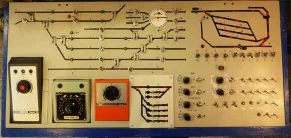
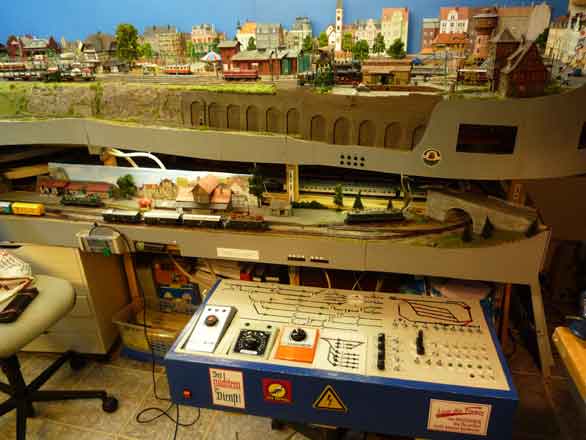
Switchbox: For the switchbox I used a big old wooden drawer with a cover made of 5mm plywood. You can see on top left the schematic drawing of the Moosbach station track plan. On the right side the plan of staging yard Zwiebelsbach with control led's for turnouts, signals and the switches beneath. Below on the left there are three throttles (DC and EMS) and a track plan of the new staging yard. This box is proven now for 15 years as very flexible to cover all changes in track plan and wiring, while the layout have changed. |
|
Throttles: The cabs have changed several times in 15 years. Of the original 3 green large Trix and one EMS throttle I have changed two of them against one electronic Trix Master throttle with WAC and a DCC system. As the DCC system is just a small box inside, I used the free space for the new control field for a hidden staging yard. Right of the throttles you see the 6 rotary switches for the Z-wiring and the switches for 2 or 3-track operation. All other switches are for light control of Bad Moosbach and the Faller-Car-System installation.
|
|
MRE Technology
2. Wiring and controlling |

|
Layout construction of the Moosbach-Rheinheimer Railway Car System |

|
3fahrt |
|
3fahrt - Dream and fiction in 1:87 |
|
A journey to the Moosbach-Rheinheimer-Railway |
|
3start |
|
3fahrt |
|
Technology |
|
Track plans |
|
Car System |
|
Landscaping |
|
Kitbashing |
|
Inside views |